August 2013
Winter is only a few months away, so in preparation for the damper part of the year I'd better get a roof onto at least one of the Midges. The decision of which to do first was simple, I already had the canvas bit for the green (Triumph) Midge. So, how to build a frame? Received wisdom indicated flat steel U shaped straps mounted on a pivot above the side of the car, this avoids encroachment into the driver's space, the inside is narrow enough already.
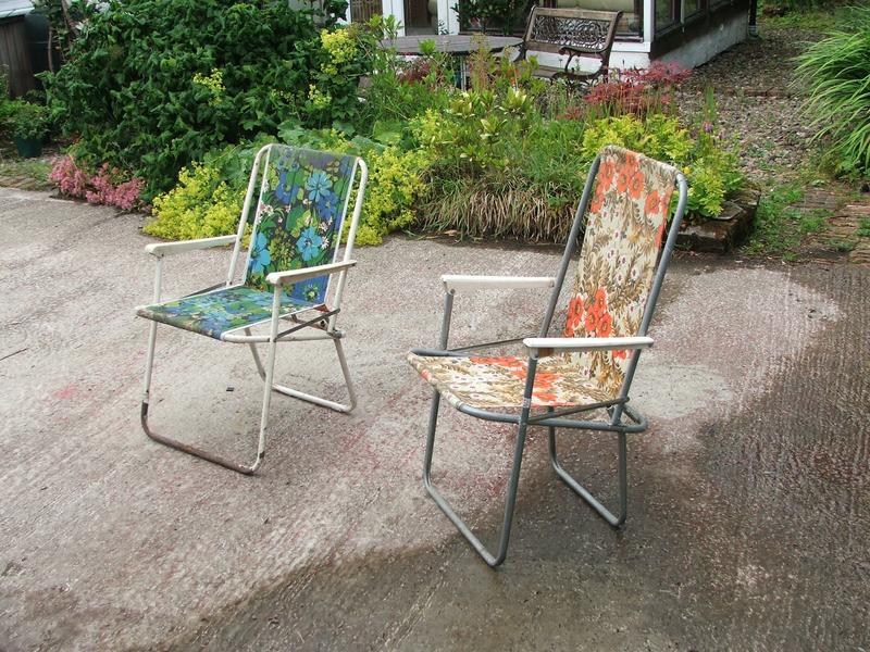
Far too easy. I prefer tube for strength, but it's difficult to flatten tube for the pivot and retain the strength, and bending it is a tad tricky without pipe bending gear. So the answer was to cannibalise something else. Hunting through the heap of "things that will have to be thrown out soon" I found a couple of old chairs.
There is another Midge to do sometime, so I tried to make one roof out of one chair.
ROOF RECIPE
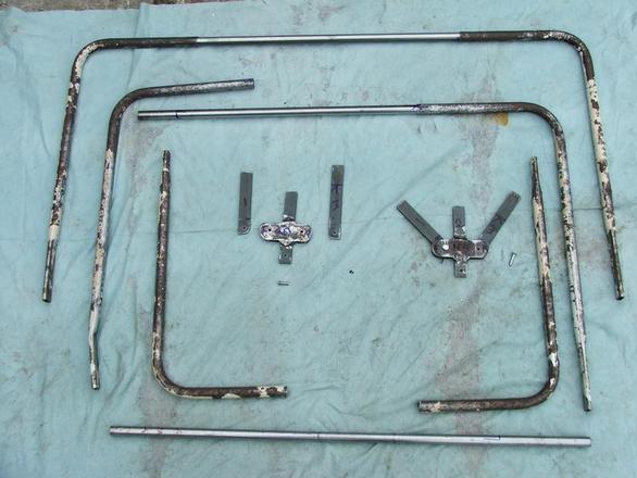
First chop a chair up. Then hunt through the stock of steel accumulated and find some 16mm (external) straight tube which fits neatly into the chair tube, and some flat (20mm by 5mm) mild steel strip which will fit the inside of the 3/4 inch chair tube if you bash it flat with a squared dummy inside.
Take care that the bashed flat bits are squared to the angle of the bend, otherwise you will find it skews when you fold it.
The result is to the right. The hinged thing in the middle (designed by and courtesy of Terry Wetherfield) is basically a bit of the flat strip welded between two bits of 3 by 30mm strip salvaged from some bits of central heating boiler with two arms pivoted on clevis pins.
Ok now, the length of the legs depends on the position of the pivot, and the width on whether it goes inside or outside the bodywork. There is a way of making it telescopic which I might try later, but I'll leave that out as being just too tekky for now.
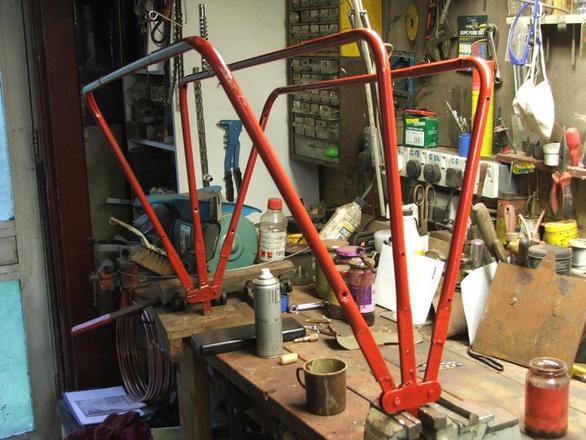
Right throw it all together and weld it up, making sure the thing lies flat, chuck some paint at it and go and have a cup of tea.
After the tea try to remember which is the front and mount the frame on pivots through the bodywork. I used bolts, but clevis pins might be better for the main pivots. Clevis pins are startlingly expensive for what they are, which is essentially shortened blunt nails with a hole through the end, so 3 of the 4 smaller ones pivoting the front and back arms are just that. Being mild steel rather than stainless, they will wear faster, but all you need is another four 6" nails, four small holes and a file. The file is for a notch to make it easier to drill the hole.
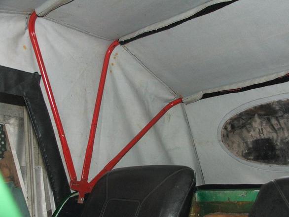
I think my roof is for a 2+2 seat Midge, having 3 hoops. A 2 hoop roof being for a 2 seater.
Having already drilled the aluminium windscreen for the studs, a tricky process that can only be classified as successful if the glass remains intact, we then sling the roof over the frame and do up the front studs and velcro bits to fix the metal to the cloth.
Square the cloth up and fix the studs at the back of the car, if they won't reach you'll need to reduce the leg length or increase the rake of the windscreen (which will upset the seal under it to the bodywork, and the windscreen wiper reach) I did those because I didn't want to lose any head clearance. The alternative being to remove one of my own lumbar vertebrae. I'll still have to reduce the chair height, but I wanted to do that anyway.
Finally you can put the side studs on. I can see that a little adjustment to a couple of studs will be required, and some kind of leather-cloth bag will be needed to prevent the slipstream from billowing the roof. If you can apply the word slipstream to a car with a top speed of 60.
Terry added a neat over-centre cam under the pivot to raise and tighten the roof. I'll do that later, but I want to increase the effect so that the whole roof can be retracted inside the bodywork. At the moment, when it is lowered, it rests on the back of the tub.
Jim's Midge roof building page.
Bashed flat bit
Donor chair
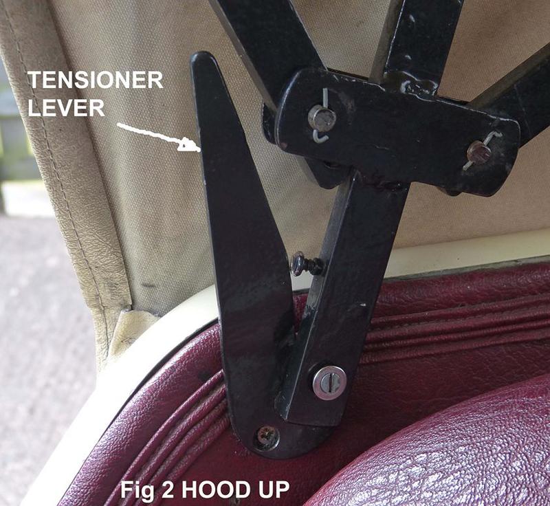
Terry Wetherfield's device,
an over-centre cam.
The roof is tensioned and relaxed by lifting and lowering the frame which is mounted and pivoted on the flat machine-screw. The cam lever in turn pivots on the pozidriv screw. The roof is shown in it's raised position. To lower the roof the lever is turned anti clockwise causing the roof to be raised slightly and then allowed to lower. The required slight lift caused by the over-centre cam prevents the device from lowering itself at the wrong time.
Self balancing of the various tensions and flexibilities are built into the four pivots shown, and the device has the advantage of being thinner than some mechanisms, but it is important to ensure that the pivots are able to take the strain. As shown the pozidriv screw might be considered too small. This problem can be exacerbated by the lever being spaced out from the bodywork to prevent the nut on the end of the machine bolt fouling the fabric. I would therefore be tempted to use a clevis pin instead of the machine-bolt, or to reverse the machine-bolt and use a domed nut in the in-board end.
Clevis pins, as are holding the two roof arms are particularly expensive, and can be difficult to source if you need a particular length. large wire nails, trimmed and filed can stand in as described above.
UP turn counter-clockwise DOWN
<< Pivot >>
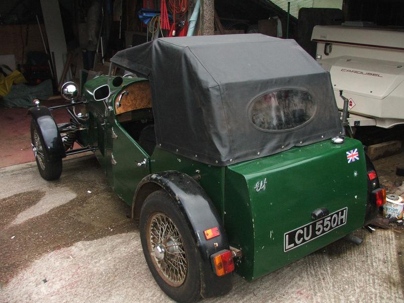
Inside or outside?. The roofs shown are mounted inside the bodywork. The advantages are that the wind catches the folded roof less and it looks tidier from the outside when folded. Theoretically it should be possible to have the roof fold neatly inside the car, although mine does not.
If mounted on the outside it would give more shoulder room and chafe the interior trim less. Terry's lifting cam might need modification.
If it was mounted on the outside I think the soft roof would need a sock (for want of whatever they were called) which keeps the folded roof clean, tidy and less likely to catch the wind. An outside mount also gives a little more space around the occupants
An entirely acceptable roof design using flat strip and requiring less engineering can be found on the Soft Roof Measurements page it uses a bracket that means the roof bars hinge down directly over the wood work. Perhaps a combination of these ideas might be worth trying.